

3D View of the Structural Steel Fame
The stage is continually being set for the upcoming construction activities. There is an important sequence of steps that occurs from visioning and design concepts to the realization of the project in its physical form. We have been through many of these to date in previous posts:
- Visioning and programming with the client and users,
- Design concepts,
- Needs confirmation,
- People, material and work flow,
- Formal solutions /floor plans, exterior and interior elevations,
- Engineering of building systems,
- Integration of architecture and engineering systems,
- Detailing,
- Construction drawings,
- Specifications,
- Contractor, subcontractors and suppliers analyzing, understanding and pricing of systems,
- Shop drawings and submittals confirming construction approach to meet design intent,
- Fabrication and assembly of materials and systems,
- Delivery to the construction site,
- Placement of materials and systems at the site.
I’m sure there are some steps left out.
Currently in the flow of the project we are in overlapping stages of:
- Shop drawings and submittals,
- Fabrication and delivery, and
- Placement of materials at the site.
The following submissions/shop drawings are currently under review at FSB:
- Fire Sprinkler System
- Aluminum Entries
- Metal Roofing
There are 125 submissions that have been submitted and processed so far.
The activities at the site to date have included:
- Earthwork and grading
- Perimeter subsurface drainage
- Cast in place concrete
- Underground plumbing,
- Underground electrical
- And the big activity that is ginning up now is structural steel.

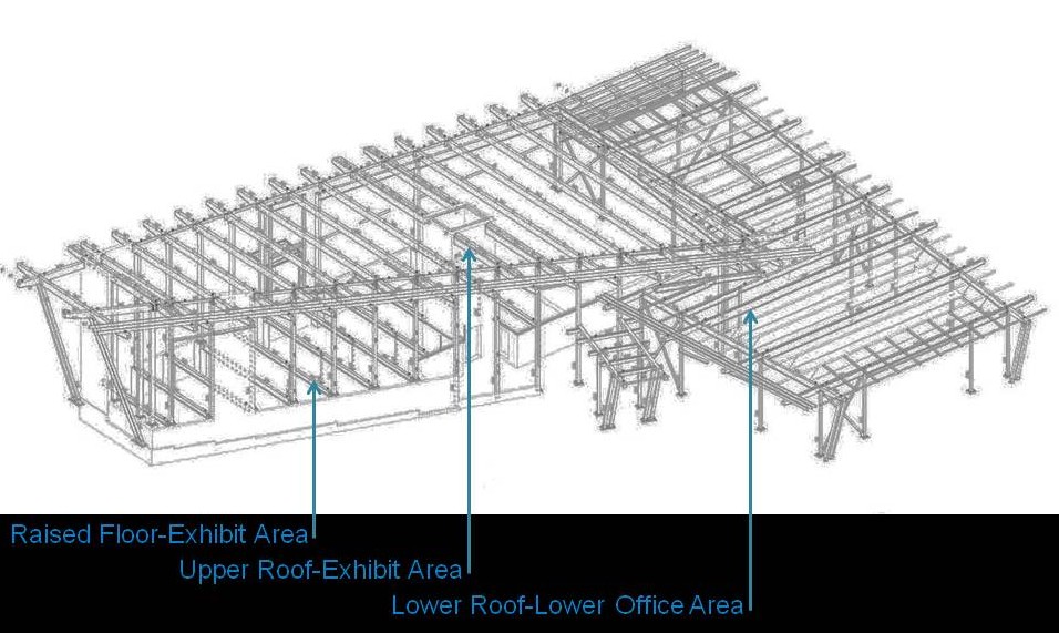
While true USGS elevations which are relative where the land sits above or below sea level are used to define the contours and topography of the site, the design industry typically sets a new vertical station of relative elevations for the building. Usually lowest level, in our case the lowest slab on grade is set at 100.0 feet. At this level we have the lower lobby and office areas on the south of the building which includes the mechanical crawl space below the Exhibit area (100.0 elevation). The next level up is the floor level of the Exhibit area gift shop, restrooms, break and conference room (107.0 elevation). The Exhibit area is on a raised floor system, while the restrooms, break and conference room areas are a higher slab on grade (over earth). The next structural level up is the roof system over the lower office area and the highest structural level is the roof system over the Exhibit area.
We have 3 different horizontal planes of structural steel (beams) along with the vertical pieces steel (columns) that hold the horizontal assemblies up. They are:
- The raised floor framing system of the Exhibit area
- The roof framing system over the lower offices
- The roof framing system over the exhibit area.
Structural submittals received at FSB include the following:
- Structural Steel Shop Drawings; Approved -10/10/2012
- Structural Steel Erection Drawings; Approved -10/10/2012
- Welding Procedure Specifications; Approved – 9/27/2012
- Welding Certificates; Approved – 9/27/2012
- Steel Joist Framing; Approved – 10/31/2012
- Steel Decking; Approved – 10/31/2012
- Cold Formed Metal Framing; Approved – 1/11/2013
The Structural Steel Shop Drawings show how each individual piece is to be fabricated and includes the size and length of the piece, any base plates, connector plates and the locations of bolt holes. The drawings also show how any of these pieces are to be welded together Click here to see a portion of the shop drawings.
The Structural Steel Erection Drawings show how all the individual pieces are assembled together. Click here to see a portion of the erection drawings.
The following series of side by side photos and shop drawings show the beam or column in the shop drawing and the same beam or column fabricated and sitting in the field at the site.


 The vertical shear walls are topped out and there is a combination of bracing and guy wires that are stabilizing them temporarily until they are tied together with the structural steel framing, raised slabs and roof systems. Without the bracing and guy wires they are susceptible to being toppled over by horizontal wind forces; the very thing that they are designed to resist once a part of the total building assembly.

 .
. .
.